CONTENTS
1.2 Purpose of the Piling Installation Plan
1.3 Structure of the Piling Installation Plan
2....... Detailed Design and Size of the Jetty
2.2 Size & Detailed Design of the Jetty
3....... Type, Number and Diameter of the Piles for the Jetty
3.1 Piles of Breasting Dolphins
4....... Details of Piling Methods
4.1 Types and Numbers of Piling Plants
4.1.1 Hammers for Piling of Breasting and Mooring Dolphins
4.3 Pile Striking and Penetration Details
4.3.1 Preparation for Pile Driving Operation
4.3.2 1st Pile Segment (P1) Lifting, Stabbing and Self Penetration
4.3.3 Hydraulic Hammer Placement onto Pile and further Self Penetration.
4.3.4 Driving of the 1st Pile Segment (P1)
4.3.5 2nd Pile (P2) Segment Lifting, Stabbing, Welding and Driving
4.4 Noise Reduction System for Hydraulic Hammering
4.5 Structural Jacket and Bubble Curtain
4.7 Response to Sighting of Marine Mammals
4.7.1 Marine Mammal within 500 m Marine Mammal Exclusion Zone
4.7.2 Marine Mammal outside 500 m Marine Mammal Exclusion Zone
5....... Environmental Mitigation Measures
5.1 Mitigation Measures for Jetty Construction
Annexes
Annex A General Jetty Layout
Annex B Hammer Specifications
Annex C Installation Vessel Specification
List of Tables
Table 2.1 Indicative Size of Key Jetty Components
Table 3.1 Summary of the Type, Number and Diameter of the Piles for the Jetty
Table 5.1 Summary of Relevant Mitigation / Precautionary Measures during Jetty Construction
List of Figures
Figure 1.1 Indicative Location of Key Project Components
Figure 2.1 Location of the Proposed Jetty
Figure 4.1 Derrick and Pipelay Barge HiLong 106
Figure 4.2 Work Flow of Pile Installation
Figure 4.3 Illustration of Pile Striking and Penetration Details
Figure 4.4 Example of Noise Reduction System for Hydraulic Hammering
Figure 4.5 Indicative Arrangement of Structural Jacket and Bubble Curtain
Figure 4.6 Indicative Setup of the Bubble Curtain
Figure 4.7 Flow Chart for Response to Sighting of Marine Mammals
To support the increased use of natural gas in Hong Kong from 2020 onwards, Castle Peak Power Company Limited (CAPCO) and The Hongkong Electric Co., Ltd. (HK Electric) have identified that the development of an offshore liquefied natural gas (LNG) receiving terminal in Hong Kong using Floating Storage and Regasification Unit (FSRU) technology (‘the Hong Kong Offshore LNG Terminal Project’) presents a viable additional gas supply option that will provide energy security through access to competitive gas supplies from world markets. The Project will involve the construction and operation of an offshore LNG import facility to be located in the southern waters of Hong Kong, a double berth jetty, and subsea pipelines that connect to the gas receiving stations (GRS) at the Black Point Power Station (BPPS) and the Lamma Power Station (LPS). The location plan is shown in Figure 1.1.
The Environmental Impact Assessment (EIA) Report for the Project was submitted to the Environmental Protection Department (EPD) of the Hong Kong Special Administrative Region Government in May 2018. The EIA Report (EIAO Register No. AEIAR-218/2018) was approved by EPD and the associated Environmental Permit (EP) (EP-558/2018) was issued in October 2018. An application for Further Environmental Permits (FEP) was made on 24 December 2019 to demarcate the works between the different parties. The following FEPs were issued on 17 January 2020 and the EP under EP-558/2018 was surrendered on 5 March 2020:
§ the double berth jetty at LNG Terminal under the Hong Kong LNG Terminal Limited, joint venture between CAPCO and HK Electric (FEP-01/558/2018/A) ([1]);
§ the subsea gas pipeline for the BPPS and the associated GRS in the BPPS under CAPCO (FEP-03/558/2018/A) ([2]); and
§ the subsea gas pipeline for the LPS and the associated GRS in the LPS under HK Electric (FEP-02/558/2018/A) ([3]).
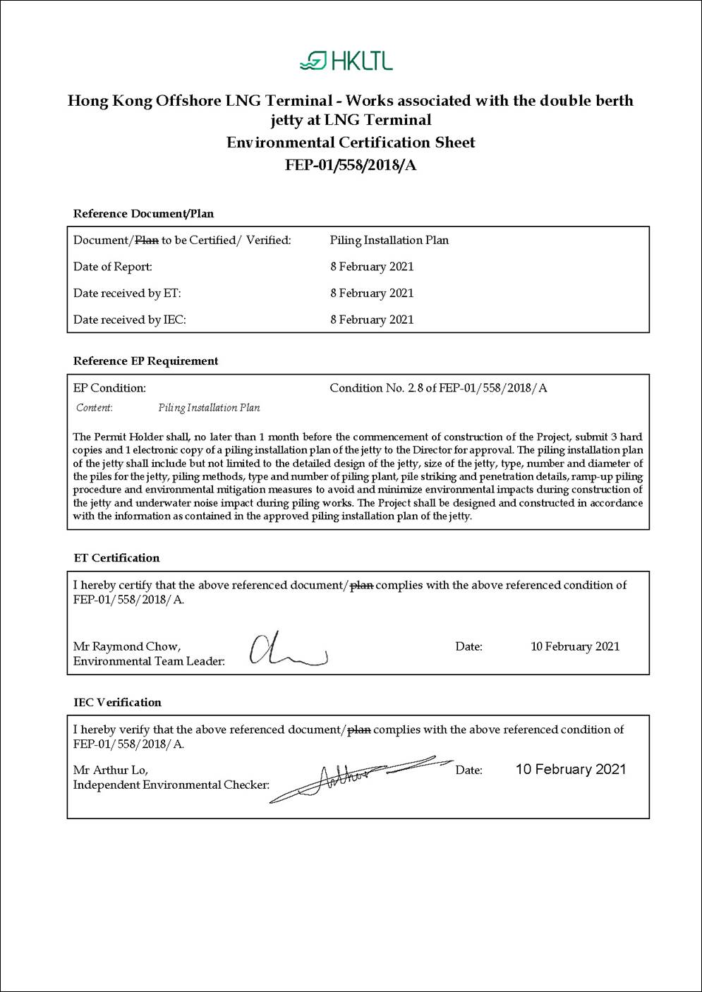
In accordance with Condition 2.8 of the FEP of the LNG Terminal (FEP-01/558/2018/A) (‘the Project’):
|
FEP No. FEP-01/558/2018/A, Condition 2.8: “The Permit Holder shall, no later than 1 month before the commencement of construction of the Project, submit 3 hard copies and 1 electronic copy of a piling installation plan of the jetty to the Director for approval. The piling installation plan of the jetty shall include but not limited to the detailed design of the jetty, size of the jetty, type, number and diameter of the piles for the jetty, piling methods, type and number of piling plant, pile striking and penetration details, ramp-up piling procedure and environmental mitigation measures to avoid and minimize environmental impacts during construction of the jetty and underwater noise impact during piling works. The Project shall be designed and constructed in accordance with the information as contained in the approved piling installation plan of the jetty.” |
As stated in Condition 2.8 of the FEP of the LNG Terminal (FEP-01/558/2018/A), this Piling Installation Plan presents the detailed design of the jetty, size of the jetty, type, number and diameter of the piles for the jetty, piling methods, type and number of piling plant, pile striking and penetration details, ramp-up piling procedure and environmental mitigation measures to avoid and minimize environmental impacts during construction of the jetty and underwater noise impact during piling works.
The remainder of this Piling Installation Plan is set out as follows:
§ Section 2 provides the detailed design and size of the jetty;
§ Section 3 details the type, number and diameter of the piles for the jetty;
§ Section 4 details the piling methods, type and number of piling plant, pile striking, penetration details and the ramp-up piling procedure, response to sighting of marine mammals; and
§ Section 5 outlines the environmental
mitigation measures during jetty construction.
The proposed jetty of the Project (“the Jetty”) is located offshore in Hong Kong SAR waters about 4 km east of Tau Lo Chau, near the Soko Islands. The water depth at the Jetty area is at least 15m which is suitable for the safe transit approach and departure of the FSRU Vessel and a visiting LNG Carrier (LNGC), and their safe berthing. The location of the Jetty is near the below key sites as shown in Figure 2.1:
§ To the north of the Jetty there are recommended traffic separation schemes (TSS), including Adamasta Channel Recommended TSS and South Cheung Chau Recommended TSS;
§ To the northwest of the Jetty there is the proposed South Lantau Marine Park (SLMP), and the Jetty is in relatively close proximity to its southeastern corner;
§ To the south of the Jetty there is open water for approximately 500m, until the boundary of the HKSAR waters is reached, and thereafter lies the South China Sea;
§ To the east of the Jetty there is the Sediment Disposal Area, which is operational and used for the disposal of uncontaminated sediment; and
§ To the west of the Jetty there are subsea telecommunications cables that span approximately 4.5 km.
The double-berth Jetty is designed to accommodate simultaneous mooring of the FSRU Vessel and a visiting LNGC. The Jetty is designed so that the FSRU Vessel can be moored on either side of the Jetty. The footprint of the Jetty marine structure including its mooring facilities is approximately 400m long and 50m wide.
The Jetty consists of the following key components:
§ Jetty substructure, including six numbers of Mooring Dolphins (named MD1 to MD6) and three numbers of Breasting Dolphins (named BD1 to BD3), for mooring of the FSRU Vessel and a visiting LNGC;
§ Jetty Topsides, comprising of an integrated unloading deck structure, Mooring Dolphins deck structure and topsides equipment such as pipe racks and firewater pump. The design of the integrated unloading deck features a two-level steel truss structure with dimensions of approximately 110 m x 50 m. The deck is divided into three main modules for ease of installation;
§ The substructures of the three Breasting Dolphins will also support the integrated unloading deck;
§ Six bridges will connect the Mooring Dolphins and the integrated unloading deck. The bridges will carry walkways and topside piping;
§ A vent stack will be installed on top of Mooring Dolphin 5 (MD5);
§ A boat landing will be provided at Mooring Dolphin 1 (MD1) and Mooring Dolphin 6 (MD6); and
§ Mooring Dolphin 1 (MD1) will accommodate the Fire Boat and Standby Boat Berth.
Details of the Jetty layout can be found in Annex A. The Jetty Substructure and integrated unloading deck, walkway bridges etc. is designed to a 50-year design life. It should be noted that the final design of Jetty has to be approved by the Hong Kong Buildings Department.
The sizes of the key Jetty components are shown in Table 2.1.
Table 2.1 Indicative Size of Key Jetty Components
|
Structure |
Size (Length × Width × Height) |
|
Breasting Dolphin |
|
|
BD1, BD2 & BD3 Jackets |
50m × 30m × 25m |
|
BD1 & BD3 Modules |
50m × 35m × 8m |
|
BD2 Module |
50m × 40m × 8m |
|
Mooring Dolphin |
|
|
MD1, MD2 & MD3 Jackets |
18m × 14m × 23m |
|
MD4, MD5 & MD6 Jackets |
18m × 14m × 22m |
|
MD1, MD2 & MD3 Decks |
12m × 11m × 8m |
|
MD4, MD5 & MD6 Decks |
12m × 9m × 8m |
|
Others |
|
|
Walkways 1 & 2 |
24.5m × 4.3m × 3.4m |
|
Walkway 3 |
59.0m × 4.3m × 4.0m |
|
Walkway 4 |
51.0m × 3.5m × 3.5m |
|
Walkways 5 & 6 |
24.5m × 3.5m × 3.5m |
|
MD5 Vent Stack |
6.0m × 5.2m × 33.0m |
A typical Breasting Dolphin pile consists of a steel tube in two segments. Thickness of the pile varies from ~45 mm to ~70 mm. Each breasting dolphin has eight numbers of about 1830 mm diameter steel open end tubular driven piles to be installed through jacket legs.
A typical Mooring Dolphin pile consists of a steel tube in two segments. Thickness of the pile varies from ~45 mm to ~50 mm. For each Mooring Dolphin four steel open end tubular driven piles of about 1830 mm diameter will be installed through jacket legs.
The type, number and diameters of the piles for the Jetty are summarized in Table 3.1. A total of approximately 54 piles of about 1830 mm diameter are expected to be installed at the Jetty.
Table 3.1 Summary of the Type, Number and Diameter of the Piles for the Jetty
|
Total Number of Piles |
Type of Piles |
|
Mooring Dolphins |
|
|
§ Four piles per Mooring Dolphin x Six Mooring Dolphins = 24 piles § Additional six piles for Fire Boat/Standby Boat Berthing at MD1 (subject to Fire Services Department and Buildings Department approval) |
§ Thickness: ~45mm to ~50mm § Diameter: ~1830 mm § Type: Steel open end tubular driven piles |
|
Breasting Dolphins |
|
|
§ Eight piles per Breasting Dolphin x three Breasting Dolphins = 24 piles
|
§ Thickness: ~45mm to ~70mm § Diameter: ~1830 mm § Type: Steel open end tubular driven piles |
Three types of hydraulic hammers have been selected for piling at the Jetty, namely MENCK MHU-800, MENCK MHU-1200 and the MENCK MHU-1900:
§ For the piles of the Breasting Dolphins, MENCK MHU-1200 will be used for pile driving while MENCK MHU-1900 will be the backup equipment in case higher driving power is required; and
§ For the piles of the Mooring Dolphins, MENCK MHU-800 will be used for pile driving while MENCK MHU-1200 will be the backup equipment in case higher driving power is required.
The specifications of these hydraulic hammers are provided in Annex B.
Jetty piles will be installed one at a time. During the piling process, only one of the abovementioned hydraulic hammers will be used.
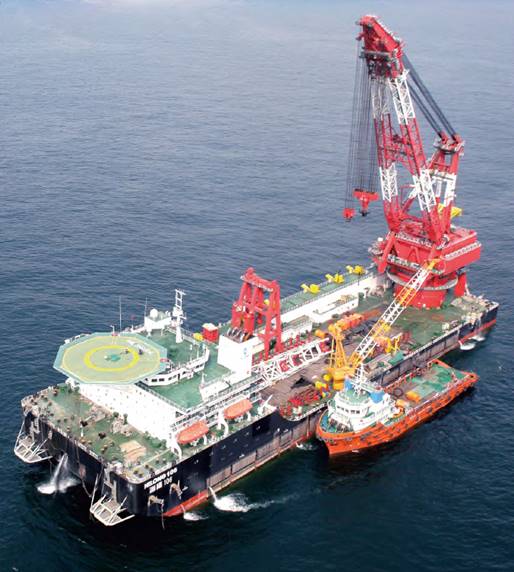
One installation vessel, Derrick and Pipelay Barge HiLong 106 (see Figure 4.1) (or equivalent) will be used for the piling installation works. Acoustic decoupling of noisy equipment (e.g. generators, winch generators, air compressors, etc) will be undertaken. The specification of the HiLong 106 is provided in Annex C.
Figure 4.1 Derrick and Pipelay Barge HiLong 106
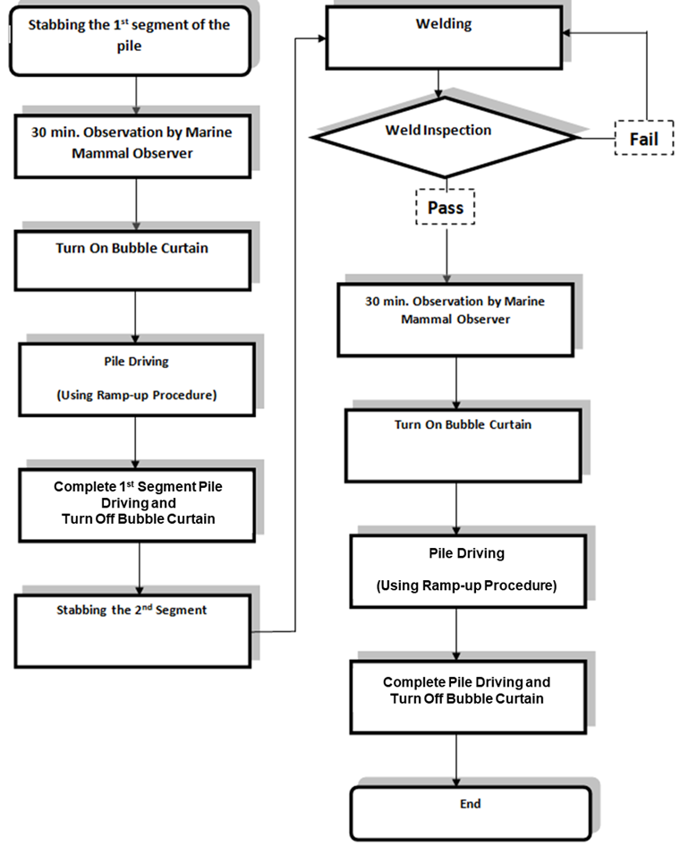
The work flow for installing a pile (total two segments for each pile) installation is shown in Figure 4.2. It should be highlighted that no piling works for construction of the Jetty will be carried out from 1900 hours to 0700 hours of the following day as per Condition 3.4 of the FEP, and no piling works for construction of the Jetty will be carried out from January to June (both months inclusive), which has been ascertained to be the peak occurrence season of Finless Porpoise in the Review Report on Finless Porpoise Peak Occurrence Season as stated in Condition 3.3 of the FEP.
Figure 4.2 Work Flow of Pile Installation
Prior to picking up the first pile the following checks will be made:
1) Obtain the initial datum of jacket level survey to determine the sequence of pile stabbing.
2) Ensure Lifting grommets and shackles and Internal Lifting Tools (ILT) are in good conditions and ready for operation.
3) Confirm that all sea fastening of the specified pile has been removed.
4) Ensure that the foreman is aware of the lifted pile to be stabbed into the designated leg of the jacket as marked at the top of the pile.
5) Ensure the hammer system has been tested and be ready for operation.
6) Ensure the bubble curtain system which encloses the piling works has been properly tested, all the workers are in place and ready for operating.
7) Marine mammal observer from the Environmental Team (ET) to ensure no marine mammals for 30 minutes continuously in sight, within the 500 m marine mammal exclusion zone from the piling installation works.
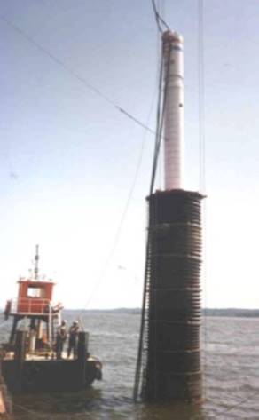
Once the jacket is checked and ready to receive the pile, the first segment of the pile (P1) is lifted up and stabbed into the jacket leg. The 1st segment of the pile will self-penetrate under its own weight into the seabed. The self-penetration is estimated to be between about 15m to 20m below seabed level based on the latest soil information and analysis.
Once the pile will self-penetrate no further, the hammer is lifted and placed onto the pile. This will cause the pile to further self-penetrate. The additional self-penetration is estimated to be about 5m and the total self penetration depth is estimated to be between approximately 20m to 25m).
Upon receiving the confirmation from the marine mammal observer that the exclusion zone is clear of marine mammals after the 30-minutes of continuous monitoring, the bubble curtain operation would be initiated. The hydraulic hammer would then be activated. The pile driving would follow a ramp-up procedure to commence driving operation and once the 1st segment is driven to depth (about 33 m below seabed level), the pile driving would stop and the bubble curtain would be turned off. The above sequences are repeated for the other P1 segments of all piles.
Once the 1st pile segment is checked and ready to receive the 2nd segment of the pile, the 2nd segment of the pile (P2) is lifted up and stabbed onto the 1st segment. Once stabbed and secured, the 2nd segment is welded onto the 1st segment. Upon completion of welding, the hammer is placed onto the combined 1st and 2nd segment. Pile driving will then be commenced following the sequence detailed in the above. The combined 1st and 2nd segment will be driven to the designed final penetration depth, at about 68 m below seabed level.
The above sequences are repeated for the remaining P2 segments.
The illustration of pile striking and penetration details is provided in Figure 4.3.
Use of Noise Reduction System for hydraulic hammering has been recommended as mitigation measure to be implemented during piling works. Specific envelope made of noise absorption/isolation material enclosing hammer sleeve will be utilized during piling works to minimise noise impact. Noise isolation pad such as rubber or cotton mat enclosing the hammer will be adopted in order to reduce noise transmission to the sea. An example of Noise Reduction System for hydraulic hammering is shown in Figure 4.4.
Figure 4.4 Example of Noise Reduction System for Hydraulic Hammering
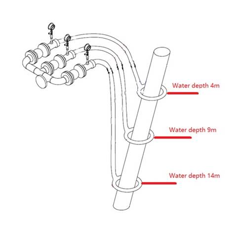
Each structural jacket has four jacket legs with diameter of ~2m for inserting piles at the Jetty. Three independent bubble-generating tubes with diameter of ~2.5m will be mounted to each of the jacket legs at ~5 m depth intervals along the water column as bubble curtains. The indicative arrangement of structural jacket and bubble curtain is illustrated in Figure 4.5.
Compressed air will be produced from the compressed air distribution and delivery unit placed on the installation vessel, and transmitted through the non-porous hoses to the bubble-generating tubes. Circular single-layer bubble curtains will be formed around the jacket legs when the valves of the bubble-generating tubes are forced to open by the compressed air for the piling works. The indicative setup of the bubble curtain is illustrated in Figure 4.6.
Figure 4.5 Indicative Arrangement of Structural Jacket and Bubble Curtain
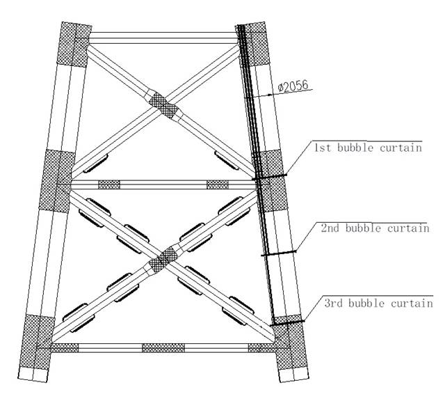
Figure 4.6 Indicative Setup of the Bubble Curtain
To avoid and minimize the impact on marine mammals due to underwater sound from Jetty pile installation works, pile driving activities using hydraulic hammers will begin with a “ramp-up” to promote avoidance of the works area by marine mammals. During ramp-up, lower hammer energy levels with a blow frequency of ~30 blows per minute will be used to start the pile driving process, and then the force of pile driving will be increased gradually.
The ramp-up piling procedure is listed below:
1) After the 500 m marine mammal exclusion zone is clear of marine mammals for 30 minutes continuously, hammer operator will turn on hydraulic hammer with a low energy level, of about 15% energy for 15 minutes.
2) Marine mammal observer continues to implement marine mammal exclusion zone monitoring and confirms that the zone is clear of marine mammals.
3) Increase the hammer energy slowly, in steps of 15% energy increase every 5 minutes until hammer energy is at 75% or design value.
4) Hammer energy to step up gradually from 75% to 95% ([4]) by ~50-100kJ intervals.
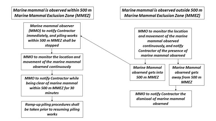
If marine mammal is observed within the 500 m marine mammal exclusion zone (MMEZ) during the piling works, the marine mammal observer (MMO) shall inform the relevant personnel of Contractor who is on site in charge of the piling works of such observation, and the piling works within the 500 m MMEZ shall be stopped immediately. Monitoring of location and movement of the marine mammal observed shall be continuously implemented by the MMO.
Ramp-up piling procedures shall be taken upon clearance of the presence of marine mammal within the 500 m MMEZ for a period of 30 minutes continuously prior to the resumption of the piling works.
If marine mammal being outside the 500 m MMEZ with potential to get into the zone during piling works is observed, the MMO shall remain in position to monitor the location and movement of the marine mammal observed continuously, and inform the relevant personnel of Contractor who is on site in charge of the piling works of such observation for attention.
If the marine mammal observed gets into the 500 m MMEZ subsequently, the same procedures as presented in Section 4.7.1 shall be taken.
If the marine mammal observed gets away from the 500 m MMEZ eventually, the MMO shall inform the relevant personnel of Contractor who is on site in charge of the piling works of such dismissal.
The flow chart for the response to sighting of marine mammals is shown in Figure 4.7.
Figure 4.7 Flow Chart for Response to Sighting of Marine Mammals
Potential environmental impacts during the construction of the Jetty and associated piling works have been identified and evaluated as documented in the approved EIA Report. The mitigation and precautionary measures during jetty construction as stated in the EIA Report and the FEP are summarised in Table 5.1 and would be properly implemented during the Jetty construction. Other mitigation measures relevant to general marine construction works will also be implemented in accordance with the Implementation Schedule detailed in Annex A of the Updated EM&A Manual.
Table 5.1 Summary of Relevant Mitigation / Precautionary Measures during Jetty Construction
|
Impact |
Mitigation / Precautionary Measures |
|
Underwater sound from Jetty pile installation works |
Use of vibratory/ hydraulic pushing method to vibrate / push the open-ended steel tubular pile for the upper layer of the seabed and only use hydraulic hammer (if needed) to install the remainder of the pile length through the lower layer of the seabed. During piling works: § Quieter hydraulic hammers should be used instead of the noisier diesel hammers; § Use of Noise Reduction System for hydraulic hammering, which fully encloses the hammer and pile during driving. Details have been discussed in Section 4.4; § Acoustic decoupling of noisy equipment on work barges should be undertaken; § Use of structural jacket and bubble curtain to enclose the pile installation works. Details have been discussed in Section 4.5; § Using ramp-up piling procedures. Details have been discussed in Section 4.6; § Underwater piling should be conducted inside a bubble curtain so as to ameliorate underwater sound level transmission; § The pile driving will be conducted during the daytime (0700 – 1900) for a maximum of 12 hours, avoiding generation of underwater sounds at night time; § Underwater piling works for the Jetty construction will avoid the peak occurrence season of Finless Porpoise (FP) as stated in Condition 3.3 of the FEP; and § Implementation of a marine mammal exclusion zone of not less than 500 m radius from the piling works during the piling works for construction of the jetty. No piling works shall be carried out until the marine mammal exclusion zone is confirmed by an experienced marine mammal observer as clear of marine mammals for 30 minutes continuously. Use of passive acoustic monitoring device shall be explored to assist the marine mammal observer to monitor and detect the marine mammals. (Note 1) |
|
Increased marine traffic from marine construction activities |
§ The vessel operators of this Project will be required to use predefined and regular routes (that do not encroach into existing and proposed marine parks), make use of designated fairways to access the works areas, and would avoid traversing sensitive habitats such as existing and proposed marine parks. Predefined and regular routes will become known to FP and Chinese White Dolphin (CWD) using these waters. This measure will further serve to minimise disturbance to marine mammals due to vessel movements; § No working vessels for construction of the Project shall enter into, transit through, stop over or anchor within the existing marine parks including Southwest Lantau Marine Park and the proposed SLMP; § The working vessels for construction of the Project shall not be operated at a speed higher than 10 knots when moving within the areas frequented by Chinese White Dolphin or Finless Porpoise, including the waters near Sha Chau and Lung Kwu Chau Marine Park, the waters at the west of Lantau Island and the waters between Soko Islands and Shek Kwu Chau; § The working vessels shall be equipped with tracking devices to record their operating speeds and marine travel routes during construction of the Project. The records shall be submitted weekly to the ET Leader and IEC for review of the acceptability of operating speeds and marine travel routes; § Any anchoring/ anchor spread requirements during Project construction will avoid encroachment into the existing and proposed marine parks; and § No stopping over or anchoring activity of vessels related to the Project should be conducted within existing and proposed marine parks even before, during and after typhoon. |
Note 1: A trial is planned to be conducted during early stage of the piling works to test if passive acoustic monitoring device will be useful in assisting the marine mammal observer to monitor and detect the marine mammals.
([1]) Application for variation of an environmental permit for FEP-01/558/2018 was undertaken and the latest FEP (FEP-01/558/2018/A) was issued on 6 November 2020.
([2]) Application for variation of an environmental permit for FEP-03/558/2018 was undertaken and the latest FEP (FEP-03/558/2018/A) was issued on 22 January 2021.